
Industrial inspection
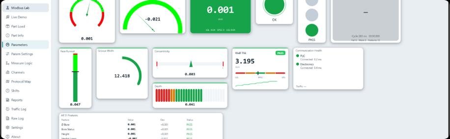
Inspection system controller and operator software
- Our scope
- PLC hardware, control firmware, operator software
- Outcome
- Deployed in India: one team for the PLC hardware, control logic and operator software.
Case study · Industrial weighing
An industrial controller that weighs vehicles in motion and combines weighing indication, thermal printing, an operator display and industrial connectivity in a single hardened enclosure.
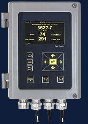
Weighbridges and in-line checkweighers have to capture a vehicle's weight while it moves, then show it, print it and pass it to other systems.
The requirement was one controller that does all of that: weighing indication, thermal printing, an operator interface and industrial connectivity, in a single hardened enclosure.
What the design had to accommodate, as recorded for the project.
Delivered by our engineering team. The client’s name is withheld for confidentiality; references are available on request. Some customer projects are contracted through our sister company, which the same team runs (see About).
Design choices recorded for this project, and what each one provides.
| Design choice | What it provides |
|---|---|
| Main controller on a six-layer board | The LPC1788 and its external memory sit on the six-layer main board, one of four PCBs in the product. |
| Isolated encoder interface | Keeps the encoder's field wiring electrically separate from the controller. |
| Brownout protection | Guards the controller against dips in the supply. |
| Bootloader | Lets the firmware be updated after the board is built. |
| Modbus RTU and Modbus TCP | Other plant equipment and software can read the controller over RS485 or Ethernet. |
Measured results from this project are not published.
Field-deployed: installed in weighbridges and in-line checkweighers, with event-wise readout in the cloud.
Related
Industrial inspection
Wireless automation
Start a conversation
Tell us what you are building and where it will be used. The first reply says which service fits and what is still unknown.