
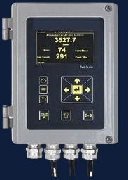
Industrial weighing
In-motion weighing controller
- Our scope
- Hardware, firmware and software
- Outcome
- Field-deployed in weighbridges and in-line checkweighers, with event-wise readout in the cloud.
Case study · Wireless automation
A three-board wireless product: a long-range transmitter that runs on a coin cell, paired with receiver hardware that switches 24 V loads at up to 10 A.
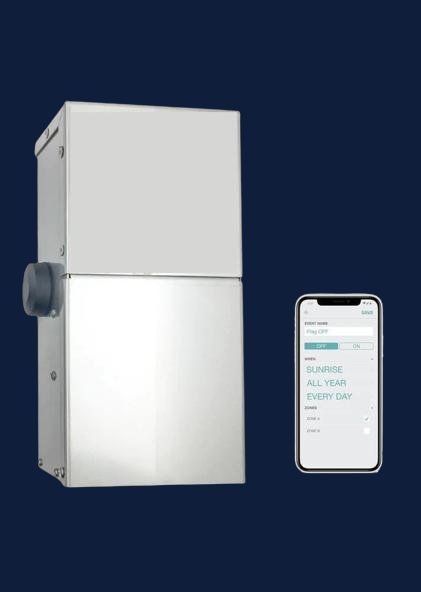
The requirement was a compact transmitter with an onboard antenna that runs from a coin cell and still reaches a long range, paired with receiver-side hardware that controls a 24 V load at up to 10 A.
The receiver had to be protected against reverse connection and overload.
What the design had to accommodate, as recorded for the project.
Delivered by our engineering team. The client’s name is withheld for confidentiality; references are available on request. Some customer projects are contracted through our sister company, which the same team runs (see About).
Design choices recorded for this project, and what each one provides.
| Design choice | What it provides |
|---|---|
| A proprietary 433 MHz protocol | The link between transmitter and receiver uses its own protocol rather than a standard network. |
| Onboard antenna on the transmitter | No external antenna on the coin-cell board. |
| Protection on the receiver power path | Reverse-connection and overload protection on the 24 V, 10 A side. |
| Other link options | Power-line communication and Wi-Fi using embedded controllers are options of the same product family. |
Measured results from this project are not published.
Delivered: the compact wireless boards, the long-range RF section, the receiver-side power hardware and protection circuits, with firmware and bring-up.
Related
Industrial weighing
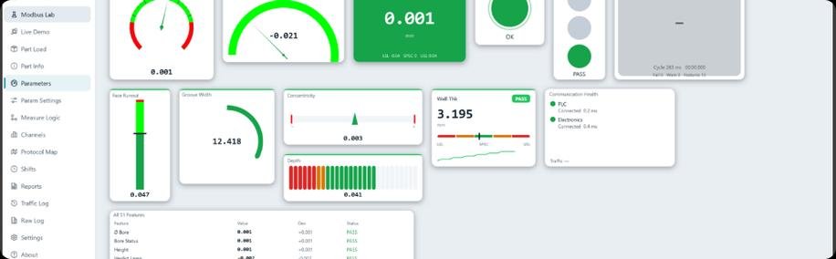
Industrial inspection
Start a conversation
Tell us what you are building and where it will be used. The first reply says which service fits and what is still unknown.